Products
Climatic Environmental Test Chamber
High Temperature Aging Tester
Ventilation Type Aging Test Chamber
Composite Corrosion Test Chamber
Formaldehyde Test Chamber
Rapid Temperature Change Test Chamber
High & Low Temperature Low Pressure Test Chamber
High & Low Temperature Test Chamber
Muffle Furnaces
Precision Oven
Sand & Dust Test Chamber
Standard Salt Spray Test Chamber
Constant Temperature & Humidity Test Chamber
Two-chamber Thermal Shock Tester
Three-chamber Thermal Shock Tester
Heat Flow Meter
UV Weathering Test Chamber
Vacuum Oven
Walk-in Constant Temperature & Humidity Room
Xenon Lamp Aging Test Chamber
Rain Simulation Water Proof Test Chamber
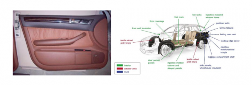
Formaldehyde VOC Emission Test Chamber
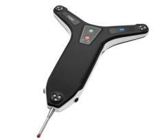
Optical Measuring Machine
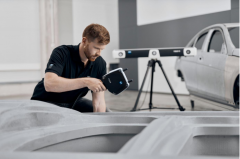
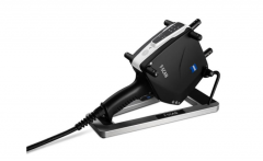
Blue Laser 3D Scanner
Water Drop Angle Measuring Instrument
Automatic Splicing Measuring Instrument
2.5D High-precision Automatic Video Measuring Instrument
Cantilever Automatic Video Measuring Instrument
Composite Coordinate Measuring Machine
2.5D High-precision Manual Video Measuring Instrument
Ultra-large Stroke Automatic Video Measuring Instrument
Fully Automatic Flash Point Apparatus
Video Measuring Microscope
Laser 3D Scanner
Digital Vertical Measuring Projector